 OpticalFlowWrapping
Non-rigidly fits a textured mesh to a textured scan by analyzing similarities between their textures.
Common Usecase
A common use case is to fit a base mesh to a set of scans of facial expressions of the same actor. This process can be usually split into two steps:
fitting a generic base mesh to a neutral expression, which can be done using Wrapping node. A texture from the scan is then projected onto the base mesh;
fitting the resulting neutral mesh to each facial expression using OpticalFlowWrapping node.
Virtual Cameras
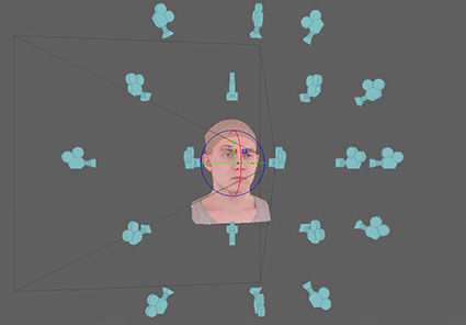
The node uses a set of virtual cameras that observe both models from different angles. For each camera, two images are rendered: one for the base mesh and the other for the scan. Optical flow is computed for each pair of images producing a set of decisions on where to move each pixel. The decisions from all the cameras are then combined into a global solution.
Wrapping vs OpticalFlowWrapping
Even though Wrapping and OpticalFlowWrapping nodes have similar inputs and parameters, there is a big difference between them. While Wrapping node only looks for geometric similarities between the models, OpticalFlowWrapping node also looks for texture similarities. For example, we need to consider texture similarities when wrapping a set of facial expressions of the same actor. For each vertex of the neutral mesh we should find its corresponding position on the target expression. If a given vertex corresponds to some specific skin pore on the neutral texture, we should find exactly the same skin pore on the target texture. The optical flow approach automatically finds hundreds of such correspondences providing almost pixel-level accuracy of alignment.
Note
It’s important that both input meshes have similar textures. To achieve that the textures should be captured under the same lighting conditions with minimal specularity.
Skin can drastically change its appearance, especially in extreme expressions. Wrinkles and blood flow effects make it hard for optical flow to find a proper solution. It’s recommended to use control points and retargeting technique in such cases.
Iterations
A computation is performed in several iterations. There are pairs of node parameters ending with “initial” and “final” word. The values of such parameters are changed with each iteration starting from the “initial” value up to the “final” value. For example resolution initial parameter is equal to cameras’ render resolution at the first iteration. The camera resolution is then increased until it reaches resolution final at the last iteration.
Projection Mask
Optical flow often causes artifacts on the borders of the mesh, especially on the neck. It leads to bad fitting and mesh distortions on the borders of the source geometry.
The projection mask option helps to prevent optical flow artifacts on the borders. This method only works if the source geometry is very similar to the target one, i.e. when the source geometry was pre-wrapped to the target.
The mask is computed by projecting the source geometry onto the target. It then paints all the pixels on the target texture with black if the pixels are located outside the projection region. As the last step, it also adds padding to the target texture to prevent render artifacts on UV seams. This small change greatly improves the OpticalFlowWrapping quality for borders.
Editor
The editor can be used to adjust camera positions, add or remove existing cameras. Single click on a camera or selecting the camera name from the camera list will switch the editor to Camera mode. In Camera mode the viewpoint is switched to a selected camera viewpoint. You can pan, zoom, and rotate in the viewport to adjust the camera position. Use Exit camera mode button to return to the standard mode.
CTRL + click on a camera will remove it.
Use transform gizmo to control position and orientation of the entire camera system.
Camera Toolbar

Camera list |
can be used to select a camera by name |
Create camera |
creates a new camera from the current viewpoint |
Remove camera |
removes a current camera. Only enabled when a camera is selected |
Exit camera mode |
exits camera mode |
Note
Fitting only works in areas of a mesh that are observed by at least one camera. The rest of the mesh is deformed as rigid as possible. Zoom in and add new cameras at the areas of interest where you want the fitting to be more accurate.
Inputs
- source geometry
GeometryA base mesh to be deformed. The mesh should have texture.- target geometry
GeometryA target scan with a texture. The textures are assumed to be similar and should be captured under the same lighting conditions.- point correspondences
PointCorrespondences(optional) A set of point correspondences between the source and the target geometry- free polygons floating
PolygonSelection(optional) A set of polygons that will be excluded from the fitting process, i.e they will not try to fit the target geometry but will be deformed as rigid as possible to match the rest of the polygons.- Mask of fixed vertices
VertexMask(optional) A vertex mask that defines which vertices on the Source Geometry should not be moved by the fitting process.
Output
GeometryFitted mesh
Parameters
- auto-compute
if set, the node will be recomputed each time a parameter or an input data is changed
- Compute
if auto-compute is off, starts wrapping process in a preview window
Camera Params Tab
- Global translation
translation of the cameras system. It can be also controlled using a transform gizmo inside Visual editor tab.
- Global rotation
rotation of the cameras system. It can be also controlled using a transform gizmo inside Visual editor tab.
- Resolution initial
camera resolution during the first iteration. It controls the size of rendered images that are then used to compute optical flow.
- Resolution final
camera resolution during the last iteration. Increasing the resolution leads to better fitting quality but at the same time drastically increases computation time and memory consumption. We recommend using values not higher than 900x900. When increasing the resolution it is recommended to also increase smoothness final parameter.
- Angle of view
angle of view of virtual cameras
- Icon size
camera icons size inside the viewport
- Clipping range
cameras’ clipping range
Camera Generator Tab
Virtual cameras are generated on a surface of the spherical sector defined by the following parameters:
- Angle
angle of the spherical sector
- Rings
number of rings of cameras inside the sector
- Cameras per ring
number of cameras inside a ring
- Radius
radius of the sphere
- Clear existing cameras
if set, all the existing cameras will be removed after clicking on Generate cameras button.
- Generate cameras
generates a set of cameras based on the parameters above
Wrapping Params Tab
- Iterations
number of iterations of the algorithm
- Smoothness initial
mesh rigidness during the first iteration
- Smoothness final
mesh rigidness during the last iteration. Increasing it will make it harder to deform the mesh during wrapping thus providing a smoother result. At the same time, it will reduce fitting quality as small scan details will have less influence over the final result.
- Fitting initial
controls the strength of fitting the base mesh to the scan during the first iteration
- Fitting final
controls the strength of fitting the base mesh to the scan during the last iteration. The fitting force is counterbalanced with the smoothness force.
- Optical flow smoothness initial
controls the smoothness of optical flow algorithm during the first iteration
- Optical flow smoothness final
controls the smoothness of the optical flow algorithm during the last iteration. Increasing this value will lead to more robust but less accurate fitting. It is recommended to increase this parameter for extreme expressions when due to big changes in skin appearance optical flow can provide wrong correspondences.
- Vertex mask weight
the scale factor for a specified vertex mask.
- Optical flow sampling
value 10 means that every 10th pixel correspondence found by the optical flow algorithm will be used. Value 1 means that every pixel will be used. Decreasing this value leads to better accuracy but greatly increase computation speed and memory consumption.
- Angle threshold
discards a pixel correspondence if the angle between the corresponding surface normals is bigger than a specific value
- Distance threshold
discards a pixel correspondence if the distance between the corresponding surface points is bigger than a specific value. Be aware that this parameter is specified in centimeters and thus scale-dependent. If you use scale other than centimeters, please adjust this parameter accordingly.
Projection Mask Tab
- Use Projection Mask
if set, a projection mask is used
- Projection Mask Dist
defines a maximal length of the projection
- Padding
defines padding size for the target texture in pixels. The padding helps to prevent render artifacts on UV seams.
Note
Distance threshold parameter is specified in centimeters and discards all the correspondences with a length bigger than a specific value. The default value 1.8 cm is optimized for models in the centimeter scale and should be changed when working with models of different scales.
Tip
The most common parameters to adjust are:
- resolution final
it increases quality but greatly increases computation time and memory consumption. It’s recommended to keep this value under 900x900. For big values, it’s recommended to increase smoothness final
- optical flow smoothness final
can be increased for extreme expressions when due to drastic changes in skin appearance optical flow fails to find good correspondences. It doesn’t affect computation time. Increase it when there’re final mesh have distortion artifacts
- smoothness final
can be increased when using bigger resolution final values. Increase it when there’re final mesh have distortion artifacts