 PointDetector
The node lets you detect input named points on another model faster, using geometry fitting, similar to BlendWrapping and auto-detecting points with a batch correspondenсes.
Input named points can be obtained using a SelectPoints node.
Two sets of named points can be combined into PointCorrespondences using a PointsToPointPairs node.
Editor
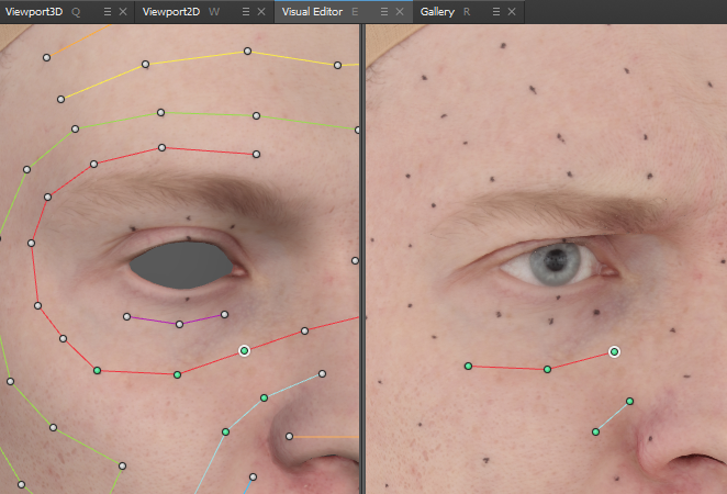
PointDetector node has an editor that allows pinning and disabling input neutral points.
Within the editor, two models are represented side by side. You can synchronize views by checking Sync views in the node parameter panel.
In neutral geometry viewport (left)
LMB |
selects points |
CTRL + LMB |
disables/enables points |
SHIFT + LMB |
unpins points |
In target geometry viewport (right)
LMB on the mesh |
pins the selected point |
LMB on a point |
selects it |
click and drag a point |
to move it |
CTRL + LMB |
disables points |
SHIFT + LMB |
unpins points |
Hold SPACE |
to show fitted mesh |
Inputs
- Neutral geometry
GeometryGeometry for neutral points- Target geometry
GeometryTarget geometry to detect points on- Neutral Points
NamedPointsOnTriangleNeutral points for neutral geometry to be detected
Output
NamedPointsOnTriangleDetected points on a target geometry
Parameters
- Auto-Compute
if set, the node will be recomputed each time some parameter or input data is changed
- Compute
if Auto-Compute is off, starts detecting process
- Accept
accepts and pins all the detected points, prevents recomputing after all points but few were detected correctly
- Reset
resets fited vertices, pinned and extra points
- Sync views
if set, synchronize left and right viewports inside the editor
Points tab
- Show Point Cycles
if set, shows in visual editor colored for each input points’ names groups
- Show Point Names
if set, shows in visual editor point’s names
- Filter
category of points shown in a list below
- All
all the points
- Pinned
only points that have been pinned to target geometry
- Fused
only points that are suspiciously topologically close to each other (usually detector mistakes)
Detector Parameters tab
- Normal Radius (cm)
radius of computing normals for setting cameras while detecting
- Camera Distance (cm)
camera’s distance away from the point on a geometry
- Point Patch Resolution (px)
pixel size of a window in which each point will be detected
- Feature Size (px)
pixel size of a point’s feature, which will be detected
Deformer Parameters tab
- Show Patches
if set, shows in visual editor currently used patches
- Patches
method of generating patches
- From Polygroups
each neutral blendshape mesh polygroup is used as the initial patch
- From Materials
each neutral blendshape material group is used as the initial patch
- Generate by Sampling
initial patches with specified radius generated on mesh topologically
- Polygroup Blur Iterations
number of iterations while blurring initial patches
- Patch Blur Weight (cm)
average adjacent weight on every iteration while blurring initial patches
- Sample Radius (cm)
radius of samples, which become initial patches, generating by Generate by Sampling method
Deformer Data Paths tab
- Show Free Polygons
if set, shows in the visual editor current free polygons
- Show Alignment Points
if set, shows in the visual editor current alignment points
- Neutral Reference
file path to neutral blend
- Blendshapes Reference
file paths to all other blends
- Free Polygon Selection
path of file with free polygon selections, which are excluded from input mesh while fitting
- Alignment Points
path of file with alignment named points, which are used for rigid alignment blends
- Save as Default
save current Detector Parameters, Deformer Parameters and Deformer Data Paths parameters as default
- Reset to Default
set current node params to default
- Reload
reload Neutral Reference, Blendshapes Reference, Free Polygon Selection and Alignment Points files